Step-by-Step Sequence
Phase 1: Preparations
- Familiarize yourself with these instructions thoroughly before you begin.
- For best results, visualize each step before actually attempting it.
- Gather all required supplies. For a complete list of required supplies & equipment see the “Media Selection and Supplies” section of this guide.
- Adjust your chair, work-surface and light for ergonomic comfort.
- Draw a series of thumbnail sketches to help you envision what your finished product will look like. As an alternative, if the scene already exists in real life, take photographs from several vantage points to help you determine the most appealing view.
Phase 2: Planning
Intro
- These instructions explain how to lay out a perspective from scratch. They do not explain how to use pre-printed, commercially available perspective grids.
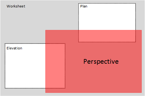
- The perspective construction process described in these instructions requires you to merge plan and elevation data together to create a perspective. If all three views (i.e. plan, elevation and perspective) are small enough, you’ll be able to fit your work onto a single sheet of paper. But that’s not always possible or advisable. Sometimes the size of paper required to contain all three views on a single sheet of paper exceeds the size of your drafting table or work surface. If that’s the case, you’ll need to separate each view onto its own sheet of paper, scale down your drawings or change the relative angle between the Plan and the Picture Plane.
- Traditionally, side views or elevations are located to the left of perspective space and plan views are located directly above perspective space. But this arrangement is neither necessary or required.
Alignment Marks
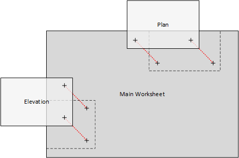
- Drafting tables and work surfaces are often disassembled and moved which means that sheets containing partially completed perspectives may need to be stored for travel and reassembled when work resumes; so if more than one sheet of paper is used to create a perspective, each must contain a set of alignment marks so the base sheet and its overlays can be perfectly realigned and reassembled.
Scale
- As you decide which scale to use, consider the following:
- The scale you select will determine the overall size of each view you draft.
- The size of your workspace (aka your drafting table or work surface) will also limit your choice of scale. Too big a scale will exceed the size of your work surface.
- The desired size of your finished perspective will likewise limit your choice of scale.
- Be consistent. Use the same scale when drafting the Plan and the Elevation.
Phase 3: Set Up
General
- Secure the sheet of paper you’ll be using to a table or drafting surface.
- Carefully measure or verify the dimensions of each object you want to draw in perspective.
- Select an appropriate scale for your drafting.
Setting Up the Elevation
- Draw an elevation showing all the objects you intend to draw in perspective. Be sure that all object heights are accurately drawn and that they’re drawn in the same scale as your plan.
- If you’re creating a perspective on a single sheet of paper, locate the Elevation near the lower left corner of your paper. If you’re drawing the Elevation on a separate sheet of paper, center your work and be sure to include alignment marks on both your elevation sheet and your main worksheet.
Ground Line
- Draw a Ground Line in Elevation and extend it into perspective space.
Drafted Heights
- Draw the side view or front elevation of every object that will be included in your perspective. As you draw, pay special attention to the heights of objects. Usually, objects are anchored to the ground but that’s not always the case (think airplanes and submarines).
- Number or label every key point on each object shown in Elevation. Be sure that all labels correspond to the same points in Plan.
- Draw construction lines from all the key points on the objects shown in elevation into perspective space.
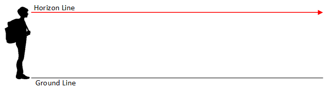
Horizon Line
- Decide how far above or below the Ground Line to place the Horizon Line. Draw the Horizon Line in Elevation and then extend it into perspective space. Make sure that you use the same scale to indicate heights as was used to draw the Plan.
Setting Up the Top View or Plan
Drafting
- If you’re creating a perspective on a single sheet of paper, locate the Plan near the upper right corner of your paper. If you’re drawing the Plan on a separate sheet of paper, center your work.
- Draw a plan or top view showing the objects you intend to draw in perspective. Be sure that all objects are accurately oriented to one another and that they’re drawn at the same scale as your elevations.
- Make sure that both the distance and the relative angle between the Objects and the Observer are drawn accurately.
- Number or label every key point on each object shown in plan. Be sure that all labels correspond to the same points in the other views.
- If necessary, label each of the key points to help keep track of construction line intersections.
- Objects may be oriented to one another in any position desired and entire Plans can be rotated to any angle. It’s imperative that you use the same scale to prepare both the Plan and the Elevation.
Station Point
- Locate the Station Point in plan. Remember that the distance between the Object and the Observer should be drawn to scale and that any angular offset between Object and Observer should also be shown accurately.
- The further away the Station Point is from the Objects, the smaller the Objects will appear in perspective. Conversely, the closer the Station Point is to the Objects, the larger they will appear in perspective.
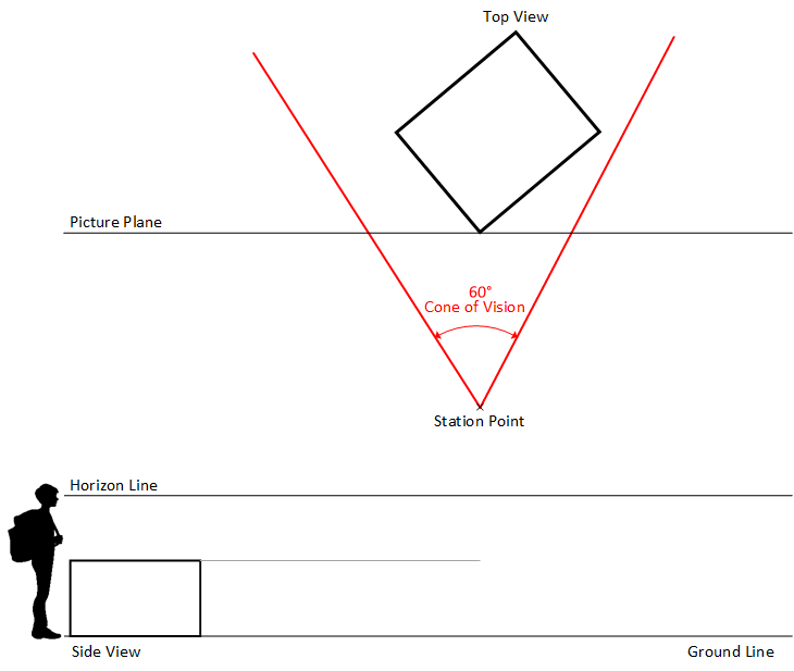
- For best results, locate the Station Point at a point that just manages to capture all the Objects within a 60 degree Cone of Vision. Remember, objects that extend beyond the Cone of Vision will appear distorted.
Cone of Vision
- Draw a 60-degree Cone of Vision anchored to the Station Point. Match the center-line of the Cone to the center-line of the Observer’s gaze (i.e. the perpendicular line drawn from the Station Point to the Picture Plane).
- Make sure that in Plan, the area you are most interested in portraying falls completely within your Observer’s Cone of Vision. Objects that fall outside the Observer’s Cone of Vision will appear distorted. Feel free to adjust the location of either the Station Point or the Plan to ensure a distortion free perspective.
Picture Plane
- Draw the Picture Plane. The Picture Plane can be positioned anywhere in relation to the objects shown in plan (i.e. it can be placed in front of, in back of, or astride of the objects in your scene).
- In most cases, it’s useful to position the Picture Plane so it touches one or more key points on objects in plan. This will allow you to bring true height information directly into your perspective from the elevation without the need for additional construction lines or projections.
- Objects located behind the Picture Plane in Plan will appear small in perspective. Objects that fall in front of the Picture Plane will appear enlarged and Objects which intersect the Picture Plane will appear normal size and undistorted.
Setting Up Perspective Space
Sheet Layout
- Locate an area in the lower right hand quadrant of your work area where you can draw your perspective. Make sure the area is large enough to accommodate widely separated vanishing points. Reminder; your perspective can be placed on its own, separate sheet of paper or it can be placed on the same sheet of paper as the Plan and the Elevation.
- Check to see that both the Ground Line and the Horizon Line have been extended into perspective space. If not, extend both lines.
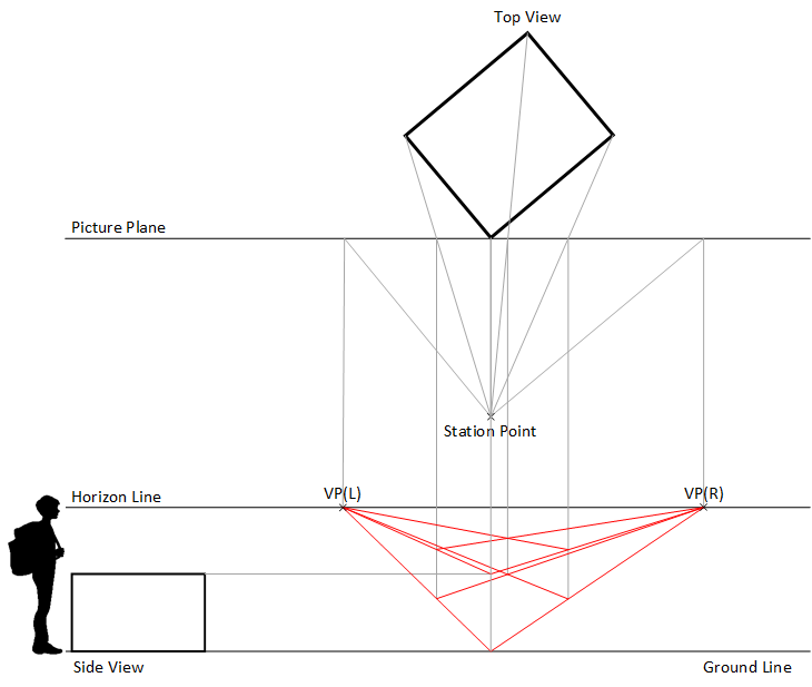
Vanishing Point(s).
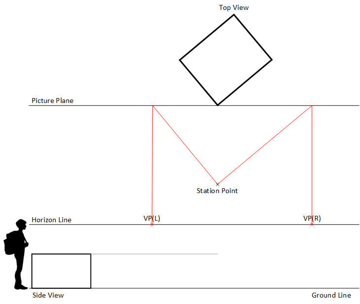
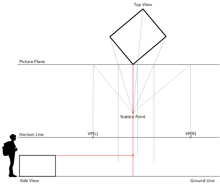
- Locate the Vanishing Point(s) on the Horizon Line. In one-point perspectives, the location of the Vanishing Point is determined by drawing a vertical line from the Station Point to the Picture Plane. In two-point perspectives, the location of the left and right Vanishing Points is determined by drawing a construction line from the Station Point to the Picture Plane from the left and from the right that are parallel to the front faces of the object that’s closest to the Picture Plane. In both one- and two-point perspectives, a construction line is then drawn vertically from the point of intersection at the Picture Plane (down) to the Horizon Line. Vanishing Points are established at the point of intersection with the Horizon Line.
- In two-point perspectives, Vanishing Point spacing is subject to a number of variables (i.e. the overall size of the objects being drawn, the scale at which they are drawn, the distance between the Station Point and the Picture Plane as well as the relative angle of the Plan to the Picture Plane); so the sheet of paper you use to create your perspective must be big enough to accommodate widely spaced Vanishing Points.
- In two point perspectives, the relative angle between the Picture Plane and Objects in Plan determines the distance between Vanishing Points. If one of those angles is too acute, the distance between Vanishing Points may exceed the width of your work-surface, in which case the angle must be adjusted; or alternatively, a way of accurately extending the horizon line beyond the confines of your drafting table must be found (e.g. railroad curves).
- In one-point perspectives, Objects shown in plan have at least one face that’s parallel to the Picture Place. In two-pint perspectives, none of the object surfaces shown in plan are parallel to the Picture Plane.
Phase 4: Creating the Perspective
Projectors from Station Point to Objects and Picture Plane
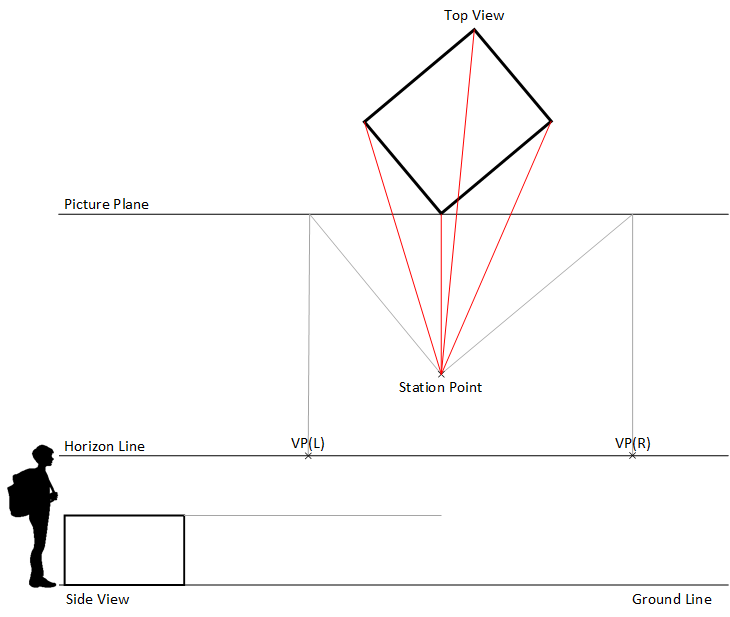
- Draw construction lines from the Station Point to all the key points on every object shown in Plan. If the Picture Plane is located behind the Objects, extend these lines until they intersect the Picture Plane.
- It may be advisable to label each of the key points to help keep track of construction lines.
Verticals
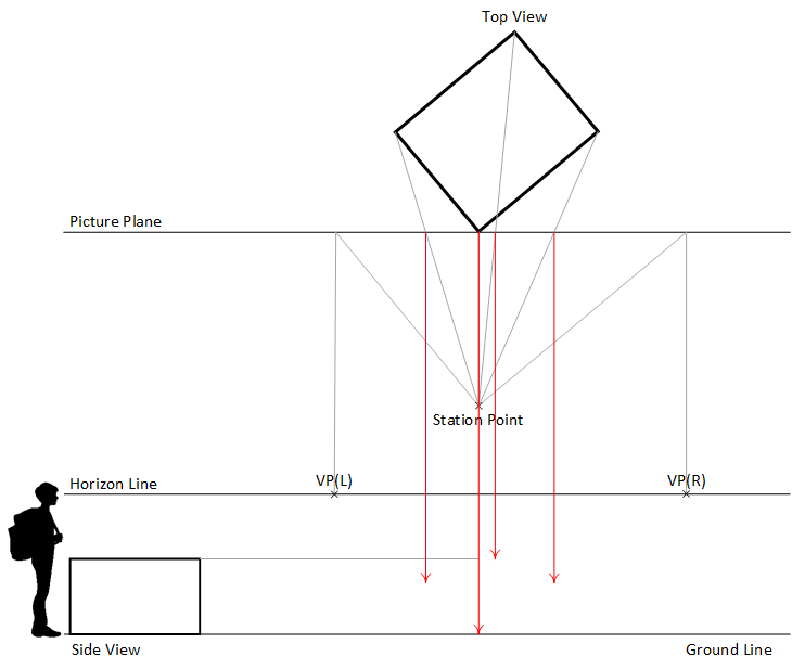
- Note where the lines linking the Station Point to the Object intersect the Picture Plane. Then, bring down vertical lines from each of these intersections into perspective space until they intersect the horizontal “height” lines that were previously projected across the paper from the Elevation or side view.
Creating True Height Lines in Perspective
- Identify any points on an Object shown in Plan that touches the Picture Plane. These points will serve as true height lines in perspective.
- If none of the Objects shown in Plan touch the Picture Plane, an artificial True Height Line must be constructed. The best way of doing that would be to extend a line from any of the object’s corners (preferably the one that’s closest to the Picture Plane), until it intersects the Picture Plane. Make sure that the extension line is parallel to the object’s surface.
- Identify the horizontal projectors coming from the Elevation that correspond to the top and bottom points on the edge of the object that’s touching the Picture Plane and note where they intersect the vertical projector that originates at the point where the Object touches the Picture Plane. The line between these two intersections is the True Height line. Darken this line.
- Extend a pair of lines from a Vanishing Point to the top and bottom of the true height line. Then, extended those lines further into perspective space.
- Identify the intersections that define the edges of the surfaces that lie directly to the left and right of the first true height line.
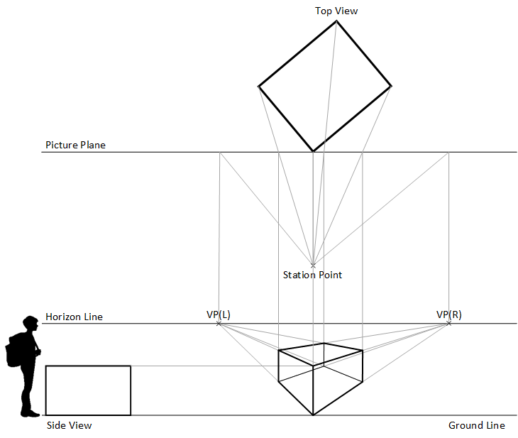
Connecting the Dots
- Draw construction lines from the top and bottom of the True Height Line to the vanishing point(s). Note where the lines going to the vanishing point(s) intersect other projection lines coming from above. These are the key points that define the perimeter of the surfaces that abut the True Height Line.
- Going from point to point, darken the outline of each enclosed surface.
- Starting from these front surfaces and working back toward the Horizon Line, locate all the other key points on objects shown in plan and draw those corresponding edges in perspective space.
- Repeat this process until all the objects shown in plan are also shown in perspective.
Good Housekeeping
- Construction lines have a tendency to proliferate as a perspective is being built so common sense and best practice dictates that that you periodically erase obsolete or unnecessary lines from your work. Obsolete lines serve to obscure and confuse more than help the process.
Phase 5: Rendering and Finishing
- Add entourage to the completed perspective.
- Clean up and make copies of the completed perspective.
- Erase any unwanted construction lines.
- Make copies of the completed perspective.
- Complete a set of practice renderings to test color palettes and media application.
- Gather all you’ve learned and apply that knowledge toward the completion of a final rendering.
