Key Concepts
1. Observer
The Observer is a stand in for the audience. He or she appears in elevation and perspective as the Horizon Line (i.e. the Observer’s eye level) and in plan as the Station Point. The Observer can be located anywhere in front of the Picture Plane, and in any position relative to the Objects being observed. The Observer’s gaze is always perpendicular to the Picture Plane.

2. Objects
Objects are the subjects of the perspective. They are what gets drawn in perspective. They can be any size or shape and they can be located anywhere in the Observer’s field of view. They can be placed as close or as far away from the Observer as desired. They can also be rotated at any angle and can also be located above, below or level with the Observer. They can also be partially obscured from view.
3. Picture Plane
Picture Plane is the name given to the surface where the perspective is drawn. Traditionally, the Picture Plane is a flat plane that’s shown in plan as a straight line. In rare instances, the Picture Plane can also be depicted as a curved line to portray a concave or convex drawing surface. The Picture Plane can be located anywhere in front of, behind or astride of the objects being drawn in perspective.
In one and two point perspectives, Picture Planes are always perpendicular to the ground plane. This is not the case in perspectives with three or more vanishing points. Nor is it the case with “oblique” map projections where the Picture Plane is obliquely tangent to the globe being mapped.
Note that the terms Picture Plane, Plane of Projection and Plane of Viewing mean the same thing and are used here interchangeably.
Traditionally, the Picture Plane is identified in Plan view with the abbreviation “PP”.
4. Horizon Line
The Horizon Line represents the eye level of the Observer. It indicates the furthest distance that can be seen by the Observer in perspective space. It also serves as the anchor for the drawing’s one or more Vanishing Points. The Horizon line is always parallel to the Ground Line and extends from the area where the elevation or side view is drawn to the area where the perspective is being constructed.
The Horizon Line represents the edge of the globe as it appears to an Observer. Because of the relatively small distances involved in each perspective drawing, the phenomenon is said to be localized which means it appears as a straight line instead of a curved edge. In other words, the distances involved are well below those that would show the actual curvature of the earth. The abbreviation “HL” is traditionally used to identify the Horizon Line.
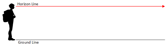
5. Ground Line (aka the Common Reference Plane)
The Ground Line (sometimes called the Common Reference Plane) provides a baseline from which all heights can be measured. It’s always positioned parallel to the Horizon Line and it extends from the side view or elevation into perspective space. Ground Lines are traditionally abbreviated as “GL”.
6. Projection Lines / Light Rays
In order to de-tangle all the construction lines that get generated during the drawing process, it’s helpful to sort them into 4 groups. The first group emanates from the Station Point and links both the Object and Picture Plane. The second group extend vertically from the Picture Plane down into perspective space. Each vertical projector starts where lines emanating from the Station Point make contact with the Picture Plane on their way to or from the Object. A third set of projectors are horizontal lines that originate in side view. They carry true height information into perspective space. The fourth set of projectors start at the Vanishing Points and extend outward. They’re used to triangulate the location of all the key points on the objects being drawn in perspective. For more detailed information about the different types of projection lines, see the “Construction Lines Explained” section in this guide.
7. Vanishing Point(s)
Vanishing Points are the place where all height lines converge. They are always located on the Horizon Line and only exist in perspective space. The abbreviation “VP” is traditionally used to label each Vanishing Point.
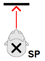
8. Station Point
The Station Point marks the location of the Observer in Plan view. It also establishes the relative location of the Observer to the Object and the Picture Plane. The Station Point may be located anywhere in relation to the Objects being portrayed in the drawing. Note however that both the Picture Plane and the Objects must be within the Observer’s gaze. As seen in plan, neither can be located behind or below the Station Point. The center of the Observer’s gaze is always perpendicular to the Picture Plane. In other words, a line drawn vertically (in plan) from the Station Point to the Picture Plane must always intersects the Picture Plane at a right angle. An “X” is traditionally used to mark the location of the Station Point in plan. In addition, the abbreviation “SP” is traditionally used to label the Station Point.
9. True Height Line
True Height Lines are only found in Perspective Space. True Height Lines are the only places in a perspective drawing where heights drawn in perspective are the same as heights drawn in elevation. They’re created when height information is projected from the Side View into Perspective Space from each of the key points on the Objects in elevation.
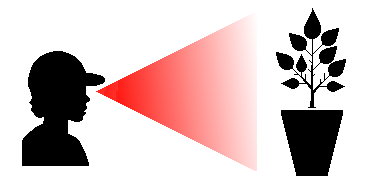
10. Cone of Vision
Human eyesight is hemispheric meaning that our field of view is roughly 180 degrees wide. However, we can only see detail within an arc that’s 60 degrees wide. Objects that fall outside this 60 degree Cone of Vision appear distorted and fuzzy. Illustrators use the Cone of Vision to ensure that the perspectives they create are balanced and pleasing to the eye.
11. Light Source / Sun
Perspectives can have any number of light sources. These light sources can be located anywhere above the Horizon Line in perspective space. Light rays emanating from these light sources are combined with projections emanating from the Solar Vanishing Point to triangulate the location, size and shape of shadows cast by objects in perspective space.
12. Solar Vanishing Point
The Solar Vanishing Point is located on the Horizon Line, directly below the Sun (or an artificial Light source). Projections emanating from the Solar Vanishing Point and the Sun are used to triangulate the location of key points of a shadow in perspective space. The abbreviation “SVP” is traditionally used to label the Solar Vanishing Point.
13. Shadows
Shadows occur when Objects block light rays traveling from their source to a receptive surface.
14. Entourage
Entourage is the name given to collections of images (either photographic or hand drawn) that are inserted into a perspective to enliven its appearance. They are a fast and cost effective way of adding detail into a rendered scene. Think of Entourage as ornaments on a Christmas tree. They don’t add structure to a perspective; they just add warmth and ambiance.
15. Linear Perspective
The term “Linear Perspective” is often used interchangeably with what most people call a “Perspective”. It’s distinguishing characteristic is that all projectors or light rays emerging from or converging into its one or more vanishing points are all straight lines. In contrast, the same projectors or light rays in a Curvilinear Perspective are arched or curved.
16. Descriptive Geometry
Descriptive Geometry is a system of rules that define how three-dimensional objects or physical phenomena are portrayed in two dimensions. Note that within this guide, the terms Descriptive Geometry and Projective Geometry are taken to mean the same thing and are used interchangeably.
17. Convergent Projections
Convergent projections are one of two major categories within Descriptive Geometry (the other being Paraline Projection). Unlike Paraline systems, projectors in Convergent systems are NOT parallel to one another, which means that will inevitably converge with one another somewhere in 3-D space. In other words, every drawn object is connected to one or more points of origin via projectors. Depending on the system employed, projectors are either straight lines (as in the case of linear perspective and most mapping systems), or curved (as used in curvilinear perspective and several other mapping schemes). The defining characteristic of Convergent Projection is that any object drawn within this system appears to recede into one or more points of origin.
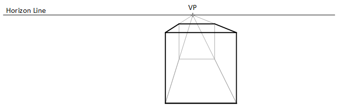
18. Single Point Perspective
Single point perspectives are a type of convergent projection. 3-D objects drawn in single point perspectives appear to converge into a single point on the drawing’s horizon. The existence of only one vanishing point is the defining characteristic of this type of projection. In one point perspective, at least one object face is parallel to the picture plane.
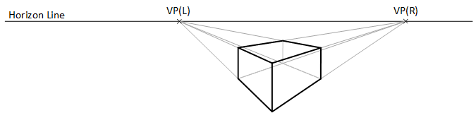
19. Two Point Perspective
Two Point Perspectives are a type of convergent projection. 3-D objects drawn in two point perspectives appear to converge into two different points on the drawing’s horizon. The existence of two vanishing points is the defining characteristic of this projection method. In two point perspective, no object face is parallel to the picture plane.
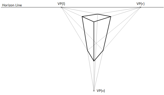
20. Three Point Perspective
Three Point Perspectives are a type of convergent projection. 3-D objects drawn in three point perspectives appear to converge into three different points (2 on the drawing’s horizon and 1 above or below the horizon line). The existence of three vanishing points is the defining characteristic of this projection method. In three point perspective (as is the case with in two point perspectives), no object face is parallel to the picture plane.
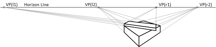
21. Multi-Point Perspective
Multi-point perspective is the term used to describe a drawing that contains several different perspectives. These perspectives are arranged so they overlap or abut one another. All share a common horizon line, ground line, picture plan, station point, plan, elevation and scale. They don’t however share the same vanishing points. To most viewers, this type of composite image is extremely life like and pleasing to the eye.
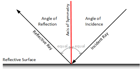
22. Angle of Incidence
The term Angle of Incidence describes the included angle that’s generated by the path a light ray takes as it travels toward a mirror and an imaginary line that extends from that light ray’s point of contact with the mirror upwards at a 90 degree angle.
23. Angle of Reflection
The angle that a ray of light travels as it bounces off a mirror is called the Angle of Reflection. It’s defined as the included angle that occurs between the light ray’s path of travel and an imaginary line that extends upwards at a 90 degree angle from the light ray’s point of contact with the mirror. In mathematical terms, the perpendicular line is called the “Normal”. The Normal acts as the reflection’s axis of symmetry. thus ensuring that the Angle of Reflection is always equal to the Angle of Incidence.
24. Axis of Symmetry
An Axis of Symmetry acts as a mirror. It splits an image into two identical halves. Each side of a symmetrical image looks exactly like the other’s mirror image.
25. Computer-Aided Design or Computer-Aided Drafting (CAD) Systems
A CAD system is a collection of specialized computer equipment and software that’s capable of portraying real or imagined objects in two or three dimensions. From their inception, CAD systems were designed to automate the process of hand drafting. They’ve proven so successful at that task that today, CAD systems have effectively made hand drafting obsolete.
26. Manual Drafting
Manual drafting is the practice of creating two and three dimensional drawings by hand using traditional drafting tools, equipment, instruments and techniques.